Project 05
RGB LED — colors and fading
The code.
// There are 2 Type:
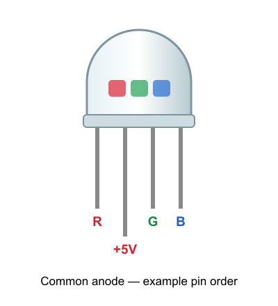
// Common Cathode (-): 	The long pin is GND (Ground). You turn a color ON by sending a HIGH signal to its pin.
// Common Anode (+): 	The long pin is 5V  (Power).  You turn a color ON by sending a LOW  signal to its pin.


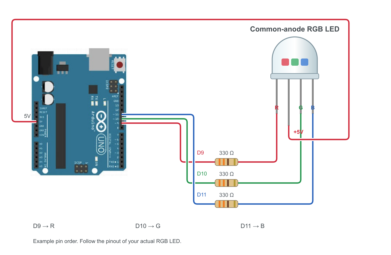
// we us - Common 5v

// Must use PWM pins (~)
const int RED_PIN = 9;
const int GREEN_PIN = 10;
const int BLUE_PIN = 11;

const int DELAY_TIME = 1000;

// Lower means faster fading. 5-10ms provides a smooth transition.
const int FADE_SPEED = 10;

void setup() {
  pinMode(RED_PIN, OUTPUT);
  pinMode(GREEN_PIN, OUTPUT);
  pinMode(BLUE_PIN, OUTPUT);

  allOff(); // Start with everything dark
}

void loop() {
  // Cycle Red
  setColor(255, 0, 0);
  delay(DELAY_TIME);

  // Cycle Green
  setColor(0, 255, 0);
  delay(DELAY_TIME);

  // Cycle Blue
  setColor(0, 0, 255);
  delay(DELAY_TIME);

  allOff();
  delay(DELAY_TIME);

  // Phase 1: Fade from RED to GREEN
  // Red goes from 255 down to 0 | Green goes from 0 up to 255
  for (int i = 0; i <= 255; i++) {
    setColor(255 - i, i, 0);
    delay(FADE_SPEED);
  }

  // Phase 2: Fade from GREEN to BLUE
  // Green goes from 255 down to 0 | Blue goes from 0 up to 255
  for (int i = 0; i <= 255; i++) {
    setColor(0, 255 - i, i);
    delay(FADE_SPEED);
  }

  // Phase 3: Fade from BLUE back to RED
  // Blue goes from 255 down to 0 | Red goes from 0 up to 255
  for (int i = 0; i <= 255; i++) {
    setColor(i, 0, 255 - i);
    delay(FADE_SPEED);
  }

  allOff();
  delay(DELAY_TIME);

}

// Modular helper to set colors using standard 0-255 logic
void setColor(int red, int green, int blue) {
  // Invert the values for Common 5V (255 - value)
  analogWrite(RED_PIN, 255 - red);
  analogWrite(GREEN_PIN, 255 - green);
  analogWrite(BLUE_PIN, 255 - blue);
}

// Modular helper to clear all colors
void allOff() {
  // 255 turns a Common Anode pin completely OFF
  analogWrite(RED_PIN, 255);
  analogWrite(GREEN_PIN, 255);
  analogWrite(BLUE_PIN, 255);
}